"Most carburetor problems are electrical"
That was told to me by a savvy old auto mechanic long ago
and it has proven true more times than I can remember.
The standard Kettering points/condenser ignition timing setup
works just fine if the point faces are parallel and clean, are
closed with proper pressure, and the condenser (capacitor is the
current term) is good and of the correct value. A lot of ifs,
don't you think? Also, unfortunately for us model engine builders,
either a grossly oversize points/condenser set from older style
lawn mower engines must be used or a miniature points set will
have to be fabricated from questionable materials and with questionable
accuracy. Most model engines don't have shaft oil seals and just
a little oil leakage onto the points will cause major problems.
Ever wonder why so many model gas engines on display at shows
are never ran? Do you suppose it's because they are easy starters
and good runners? Some may be. But how many really otherwise great
engines won't run or are so hard to start because of ignition
problems, that the owner won't even bother? What a shame! If you
don't like having your engines ending up as just shelf models,
then keep reading!
I came across the answer some years ago in a magazine article
written by Floyd Carter and all my spark plug ignition model gas
engines use it with great results. The original Transistor Ignition
Module (TIM - 4) is a simple two transistor circuit that can easily
be home built. TIM-4 was designed to operate on 3.6 volts (three
Ni-Cad cells in series) for use with model airplane engines. It
eliminates all the problems of standard points systems. The coil
will give a good hot spark every time. The circuit requires very
little current to trigger (25 ma). This allows use of a tiny micro
switch for the points which can be easily hidden. There is no
arcing, so the contacts in the micro switch will never burn. If
you want your model antique engine to be authentic, or on already
built engines which you don't want to change, the old point set
can be used if desired. A "condenser" is not needed
but can be included for looks.
And now for the really BIG advantage........
Since we now have a circuit that is so easy to trigger, we can
use a tiny magnetic sensor instead of mechanical point contacts
(high amperage switch)! The magnetic sensor is called a "Hall
Effect Device". They are really tiny, measuring just .125"
x .170" x .060" thick (3mm x 4.3mm x 1.52mm). Instead
of a cam to operate contacts, a tiny magnet (only 1/8" diameter
by 1/16" thick - or smaller) mounted on a drum or disk (cam
gear) triggers the Hall device which is mounted in close proximity.
The Hall sensor is located remote from the circuit board which
can be hidden under the engine, or wherever you wish. Now you
have the ultimate in small and reliable ignition, no mechanical
parts, rub blocks or contact points at all! The circuits are extremely
reliable.
Floyd is a retired aerospace electronics expert now enjoying life
and intends to continue doing so. He sells his TIM-4 units ready
made. He does not make any of the units available as kits. There
is actually nothing at all difficult in building these circuits
except a little care and the exercise of some common sense. With
some help and advice from Floyd (and against some!) I am making
these kits available under the following conditions: If you are
not profiecent at soldering, don't have a 25 to 35 watt (max.)
soldering pencil (no 150 - 300 watt solder guns), don't have some
previous experience with electronic parts and circuit boards,
then you probably shouldn't order these kits because I
positively will not replace any damaged part at my expense for
any reason. I will sell replacements for damaged parts at very
reasonable prices in the unlikely event that you should need them.
I changed some of the components of the original TIM unit
for 6 volt operation on stationary engines. I designate this as
the TIM-6.
To run an engine with electronic ignition you will need: TIM-6
module, a suitable 6 volt ignition coil (see below), spark plug
and a good 6 volt battery that can supply at least 5 amps.
These ignition modules may be used on multi
cylinder engines if model ignition coils such as the Exciter,
Modelectric or Gettig and having a primary winding resistance
of not less than 1 ohm. This combination runs my V-Twin, V-Four
and other engines with no problems at all.
If you want to use automobile or motorcycle ignition coils with
a primary winding resistance less than 1 ohm, use a proper ballast
resistor in series with the coil so the current draw is not over
4.5 amps.
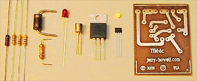
TIM-6
- For use with 6 volt batteries
(or 4.8 minimum to 7 volts maximum) on any engine type. The kit
contains: (1) TIP42C Transistor, (1) 2N2907A Transistor, (4) Resistors,
(1) LED Timing Light, (1) 3 Amp. 40 volt reverse polarity protection
diode, (1) Hall Effect Magnetic Sensor, (1) Length of Heat small
plastic tubing to insulate the Hall Sensor leads, (1) Rare Earth
Magnet, (1) Drilled Printed Circuit Board, Circuit Diagrams and
Construction Notes. The circuit board is approximately 1.35"
wide by 1.70" long. Just to the left of the circuit board
is the Hall Effect sensor and the dot just above it is the rare
earth magnet which is just 1/8" in diameter and 1/16"
thick (3.2mm x 1.6mm).
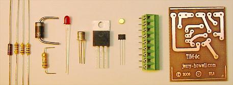
Deluxe TIM-6c
- Same as above, except
also includes a high quality PCB
Screw Type Terminal Strip for ease of connecting or removing your
battery, coil, and other wires.
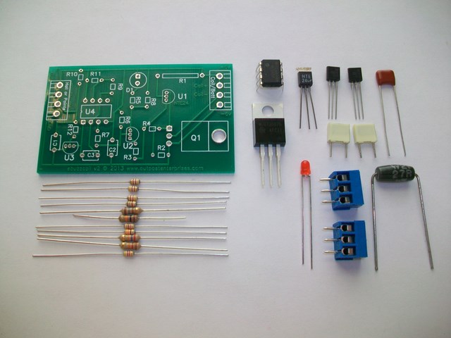
Deluxe TIM-6 kit components
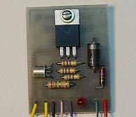
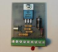
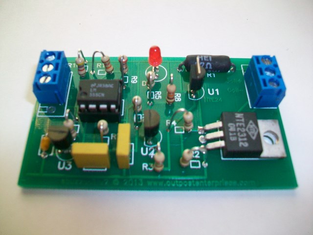
Deluxe TIM-6c assembled unit
Deluxe TIM-6 Kit - Only $25.00 Assembled & Tested - $40.00
(Use the Kits
& Parts Order Form to place an order. Otherwise, see
the "How To Order" page)
Electronic Buzz Coil
-
Back by popular demand is a new, improved electronic buzz coil ignition
module. What's a "buzz coil"? It's very similar to the
TIM-6 ignition module except that instead of generating one spark for
each power stroke, the buzz coil can generate dozens for each
power stroke (200 per second - duration depends on the "dwell angle").
This greatly improves combustion for slower hit-and-miss or older
engines that may not have much compression. The new PCB is
slightly larger than Jerry's original and displays part outlines and
labels for easier assembly. Also included are wire terminal
blocks to make wire hookup much easier.
For use with 6 to 12 volt batteries and coils.
Kit
contains: (1) NTE2312 Transistor or equivalent, (1) NTE24
Transistor, (2) 2N2907A Transistors, (12) Resistors, (1) LED
Timing Light, (1) LM555CN Timer IC or equivalent, (3) Capacitors, (1)
Drilled Printed Circuit Board, (2) Screw Terminal Blocks, Complete
Assembly and Installation Instructions with Diagrams and Construction
Notes.
The
circuit board is approximately 1-1/2" wide by 2-1/2" long. Since
many builders connect these to their "points" system, the kit does NOT
include a Hall sensor or magnet as these may not be needed.
However, if you are not using "points", be sure to order a Hall
and magnet from the "Ignition Systems" menu. Order an extra Hall
sensor and magnet if you wish to use the "spark saver" option.
Buzz coil kit components
Buzz coil assembled unit
Buzz coil Kit - *New Lower Price* Only $30.00 Assembled & Tested - $55.00
(Use the Kits
& Parts Order Form to place an order. Otherwise, see
the "How To Order" page)
u
Ignition Dwell Angle
- A rule of thumb to calculate dwell angle is Cam
Shaft RPM x .0075 for 4 cycle engines, or Crankshaft
RPM x .0075 for 2 cycle engines. This will determine the
shaft rotation in degrees that the coil should be energized (points
closed or Hall Sensor turned "ON"). Too little dwell
angle will limit top engine RPM as the spark will be weak or non
existant - too much dwell angle will overheat the coil and electronics
at low RPM. A simple calculation or two will determine the radius
from the center of the shaft to mount the magnet and Hall Sensor.
High speed engines need small radius (or several magnets in an
arc) to get enough dwell angle, slow running engines require greater
radius (or a smaller magnet) to prevent excessive dwell angle.
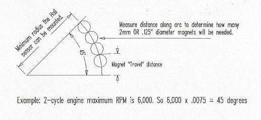
Calculate the dwell angle for the highest expected engine RPM.
Therefore, if a 2-cycle engine has a top RPM of say 6,000 RPM,
then .0075 times 6,000 = 45 degree dwell angle. In the above case,
draw a circle representing the smallest radius you can mount magnets
in a disk and also have a Hall sensor mounted at the same radius.
Engine features will determine this. Draw the 45 degree angle
lines from the center of that circle. The arc on the circle between
the 45 degree lines is the length of arc you need to have magnets.
For a 4-cycle engine at 6,000 RPM, use the cam shaft speed of
3,000 RPM which gives a 22.5 degree dwell angle. If the Hall sensor
can be mounted so that it can be rotated around the center of
the shaft, ignition timing can be adjusted for "advance"
or "retard". Try to get the dwell right for a nice running
engine. See the diagram below.
Very few model engines will need more than one magnet to obtain
correct dwell angle - none of my engines needed more than one
magnet/cylinder.
The following measurements are for the Hall sensors and magnets
that I currently have available.
TIM-6 magnets are 1/8" dia. by 1/16" thick. With the
1/8" dia. rare earth magnets at .030" away from the
Hall Sensor face, the sensor will be turned "ON" during
the time it takes for the magnet to move .125" across the
sensor face. In other words at a certain point, as one edge of
the magnet starts to move cross the Hall sensor face, the sensor
will turn "ON" and stay "ON" until the 1/8"
diameter magnet has moved across the Hall Sensor face for a distance
of .125". As the magnet moves beyond that point, the Hall
sensor will turn "OFF" again. The distance the magnets
move during turn "ON" does not change significantly
with the magnets from .025" to .035" from the Hall Sensor,
so distance away is not that critical.
For the 2mm diameter magnet at a distance of .030" away from
the Hall Sensor face, the Hall Sensor will be turned "ON"
during the time it takes for the 2mm dia. rare earth magnet to
move a distance of .050" across the face of the sensor. All
these measurements were made using the DRO on my milling machine.
More info is in Strictly I.C. magazine #27 and #36. Back issues
available robert@strictlyic.com
PLEASE NOTE - I get asked a lot of
questions about using these ignition modules on chain saw, weed
eater and other non-stationary and/or non-model engines. Many
of these types of engines have been converted and are operating
in various applications. However, I make no claim of suitability
of any of the above ignition units for non-model engines. Some
of these engine types may be suitable and some may not be. If
you want to convert these engines, you are on your own, so you
should consider the use of these ignition modules and/or coils
on non-model engines to be experimentation on your part. Please
also note - electrical items are not returnable for refund for
obvious reasons.
With the above understanding, you want to go ahead anyway,
here are some guidelines. With the right battery voltage and -
very important - an ignition coil with a primary resistance of
not less than 1 ohm, I see no reason why an enterprising person
shouldn't be able to convert most, if not all, of these engines.
In a nutshell, determine from your engine the minimum circle diameter
you can use to get the proper dwell angle (see above) from the
rotating magnet(s) which are mounted on a drum or disk somewhere
on the crankshaft (2 cycle) or cam shaft (4-cycle) and suitable
mounting of the stationary Hall Sensor in close proximity to the
rotating magnet(s) and make that installation. That is all the
modification you need to do to a single cylinder engine. There
are many ways to set up multi-cylinder engine ignition systems.
Usually multiple magnets and a distributor are required. Again,
I don't do consulting so you are on your own. Also, if you intend
to use the engine with radio control, remember that the entire
ignition system - TIM module, coil, plug wire, plug, etc. should
be shielded and grounded to the engine to prevent radio interference
and possible loss of control of your model. On the other hand,
I have talked to some fellows who say they have not found this
necessary with their particular radio by installing the radio
as far aft in the plane fuselage as possible.
You decide what you are comfortable with. Good
luck....