Jerry E. Howell Model Project Plans & Kits
Outpost Enterprises, LTD - 695 Godfrey Road - Hollansburg - Ohio 45332 - USA
(World Wide Supplier of Quality Model Project
Plans & Kits Since 1992)

"Howell V-Four" Engine Camshaft Assembly
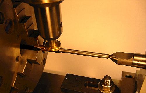
Center the cam shaft under the mill spindle. A 5/8"
long split bushing flush with the end of
the shaft accurately spaces the first cam pair. This is the gear
end of the shaft. The rotary
table degree setting is set to zero. With Loctite on the shaft,
the proper cam pair is twisted
on the shaft and with the lobes on top. The exhaust lobe will
be against the split sleeve and
pointing away from you. The Cam Setting Tool is brought down to
accurately set the 'zero'
line across the lobes. Let the Loctite set 15 minutes.
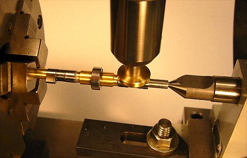
Dial the rotary table 180 degrees. Retract the tail center and
using Loctite, install
bearing spacers and center bearing. Install the cam pair as before.
The exhaust lobe
will be facing the tail center and pointing away from you. Bring
the tail center back
up and set the cam pair 'zero' line as before.
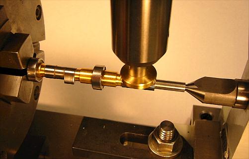
Remove the split sleeve and reverse the shaft in the 3-jaw chuck.
Leave the chuck
jaws just a little loose and 'zero' the first cam pair, then tighten
the chuck jaws. In
the photo, I should have left the radiator end bearing off untill
later.
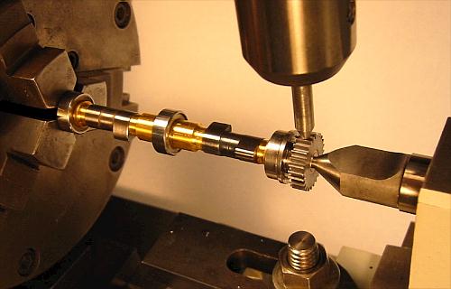
Rotate the rotary table either 3.4 degrees (3 degrees 24 minutes)
or 6.9 degrees
(6 degrees 54 minutes) depending on which shaft you are doing.
Make a timing punch
mark at a tooth of the gear as shown on plan sheet #28. Count
the number of teeth
clockwise depending on which shaft you are doing and scribe a
line between the next
two gear teeth for later identification. Change from the Cam Setting
Tool to the Gear
Setting Tool. Install the spacer, bearing, and then the gear with
Loctite. Rotate the gear
so you can bring the setting tool down between the gear teeth
where the scribed line is.
© Copyright - 2006 - 2007 Jerry E. Howell
- All rights reserved